1528+
MWp Capacity435+
Projects1528+
MWp Capacity435+
Projects1528+
MWp Capacity435+
Projects1528+
MWp Capacity435+
Projects
1528+
MWp Capacity435+
Projects1528+
MWp Capacity435+
Projects1528+
MWp Capacity435+
Projects1528+
MWp Capacity435+
Projects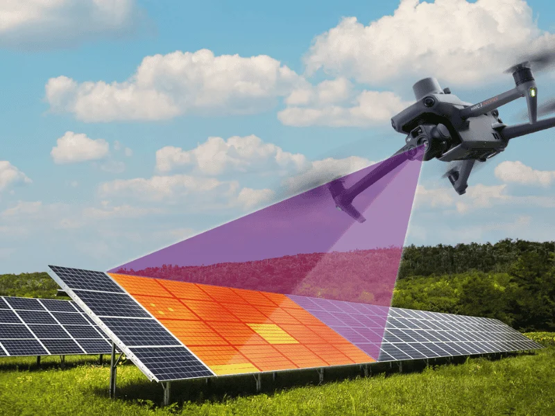
In solar asset management, accurate equipment condition assessment is the cornerstone of sustained performance across a 20-25 year operational lifespan. A thermal imaging camera enables engineers to localize thermal anomalies without physical intervention, enabling timely root cause analysis and eliminating recurrence risks.
This article analyzes the role of this technology and the 7 most common faults detected in the field by Electric Bird’s technical team.
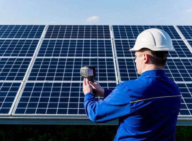
A thermal imaging camera (also known as an infrared thermal camera) is an essential diagnostic tool for solar system inspections. It identifies thermal anomalies across equipment without direct contact, making it one of the most efficient non-destructive survey methods available. A single thermal scan can detect multiple types of abnormalities across modules, strings, and DC/AC combiner boxes before they progress into fire hazards or serious equipment failures.
Applying this technology delivers several core values for asset owners:

Collecting reliable temperature data requires strict adherence to field conditions. Deviations in irradiance or equipment calibration will compromise the validity of trend analysis.
Key conditions technical teams must observe:
Applying infrared thermal imaging in O&M operations enables the digitization of physical asset condition. Below is a detailed technical analysis of the 7 most frequently identified fault categories.

Phenomenon: Mechanical impact or thermal stress causes glass breakage, internal silicon micro-cracks, or delamination of the EVA encapsulant layer.
Thermal signature: Temperature elevation along hairline micro-crack patterns or uneven heat distribution at delamination zones.
Consequence: Even when no immediate critical fault is triggered, structural defects drive performance deviation from the Year 1 baseline. These defects inevitably compound into cumulative production loss across annual cycles if left uncontrolled.
See also: How to Inspect Solar Panels Using a Thermal Imaging Camera and SCADA
Solar energy assets typically carry a 20-25 year operational lifespan. However, unstructured operations lead to escalating OPEX driven by the absence of a long-term O&M strategy. A credible solar operator focuses on risk governance rather than reactive repair after faults occur.
Electric Bird provides specialized solar O&M and asset management services. We integrate periodic thermal imaging camera inspections to detect latent risks early, optimize operational performance, and reduce degradation risk across full operating cycles.
Rather than conventional maintenance approaches, our solar operations framework centers on KPI-based performance monitoring and seasonal trend analysis, keeping PR, availability, and downtime metrics within controlled thresholds. We commit to maintaining performance within contractual bounds, delivering sustainable returns on your project investment.
The difference between a performing asset and an underperforming one often comes down to how early risks are identified. Thermal imaging camera inspections, combined with structured pv repair workflows and SCADA-integrated monitoring, form the diagnostic foundation for protecting long-term asset value.
Effective thermal imaging camera inspections, structured pv repair protocols, and KPI-driven monitoring are the three pillars that separate reactive maintenance from professional asset management.
If you want to protect your solar investment and maintain performance across its full lifecycle, contact Electric Bird to learn more about our specialized O&M and asset management services.
A thermal imaging camera is a non-contact diagnostic tool that detects latent risks before they escalate into fire hazards or serious failures. Scans should be performed during high-irradiance periods above 600 W/m², when thermal stress anomalies on inverters and modules are most clearly visible.
Hotspots represent localized cell degradation and are a direct cause of cumulative production loss that compounds annually if not addressed by the technical team through timely pv repair or module replacement.
Thermal imaging enables engineers to detect open-circuit strings and overheating MC4 connectors or fuses that are invisible to the naked eye. Early detection prevents fire risk and significantly reduces mismatch loss.
The absence of SCADA alerts does not mean your asset is operating at its optimal baseline. Hidden faults such as PID, micro-cracks, or localized shading may be causing progressive performance deviation that no alarm will flag until significant losses have already occurred.
Inspection frequency depends on plant size, age, and environmental exposure. As a general framework, Electric Bird recommends at least one comprehensive thermal imaging camera survey per year, supplemented by targeted checks following severe weather events or sustained production underperformance.
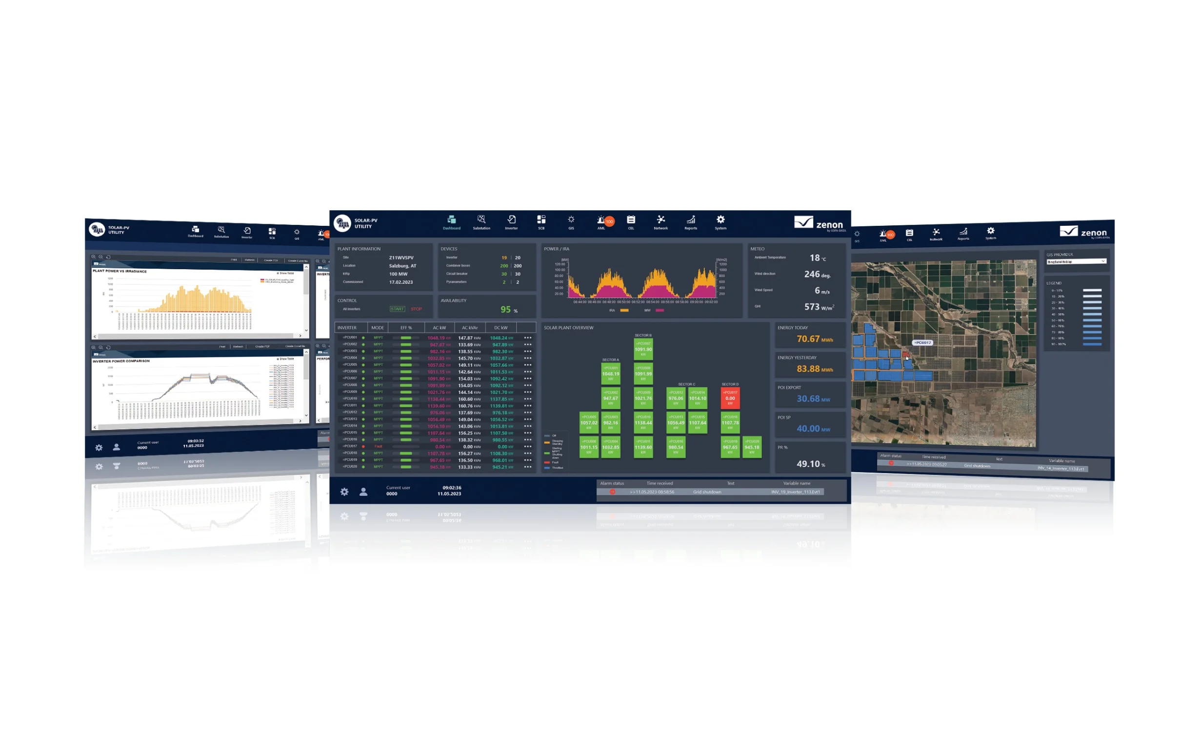

During the investment and operation of solar power plants, many businesses confuse monitoring with SCADA. While both serve the purpose of system oversight, these two platforms differ significantly in terms of functionality, control capabilities, and operational support. For large-scale projects in particular, understanding the role of SCADA in a solar power system helps investors optimize […]

In the digital energy era, managing a solar power plant goes far beyond reading basic performance metrics. An AI-integrated SCADA control system shifts the entire operational model from passive data collection to active predictive intelligence, giving asset owners a decisive edge in protecting long-term returns. From Reactive Monitoring to Predictive Intelligence Most conventional SCADA control […]
Most solar panel businesses reach commercial operation and immediately shift focus to the next project. The system is running, the inverters are green, and the monthly report shows output. But here is the uncomfortable reality: a system can appear operational while silently losing 5 to 15 percent of its annual yield, and the owner never […]